Accessories | Electronics Matek Matek – Crsf To Pwm Converter (6 Type)
$9.30 $7.44
Accessories | Electronics Matek Matek – Crsf To Pwm Converter (6 Type)

Crsf-Pwm Converter, Crsf-Pwm-6
- Compatible With Crsf Protocol Receiver Only
- Support Any Crsf Protocol Receivers (Including 433Mhz, 868Mhz, 915Mhz, 2.4Ghz)
- 6X Pwm Outputs
- Pwm Frequency Configurable (50Hz Default, 100,160,330, 400Hz)
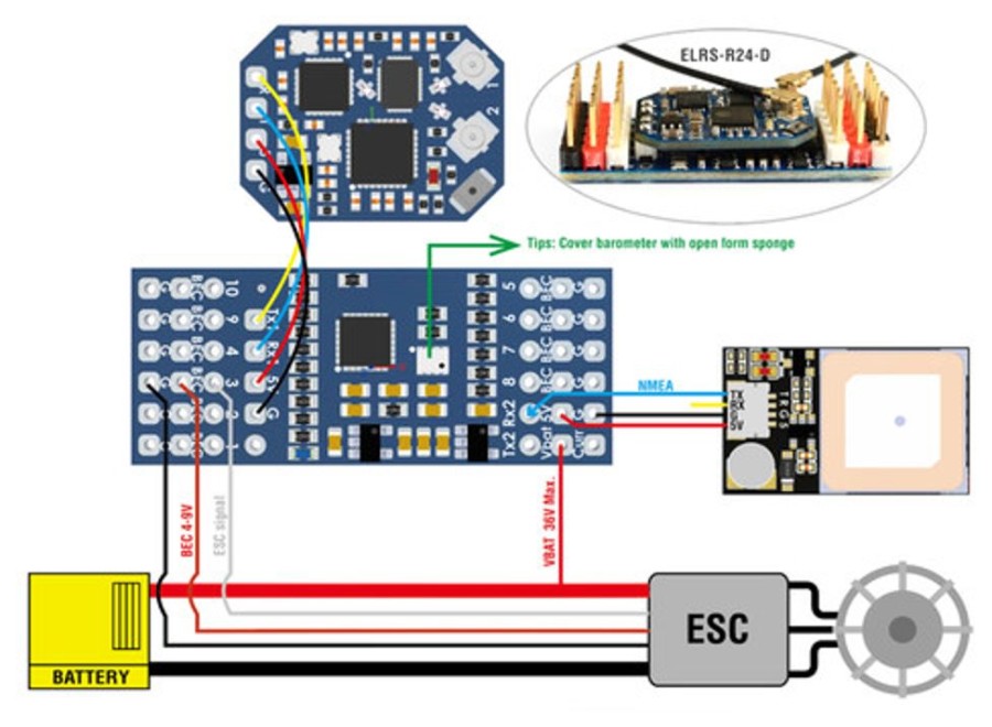
- 2X Uarts (For Receiver And Gps)
- Telemetry Id: Rxbt, Curr, Capa, Bat%, Gps, Gspd, Hdg, Alt, Sats
- 36V Max. Battery Voltage Sense (1K:10K Voltage Divider Built-In)
- Compatible With External Current Sensor (0~3.3V)
- Vbat And Current Sensor Scale Configurable
- Failsafe Value Auto Set
- Firmware Upgradeable
- Rated Voltage: 4~9V @5V Pad, 0~36V @Vbat, 0~3.3V @Curr
- No 5V Regulator Built-In, Servos Must Be Powered Via 5V Pad By External 5V Source.
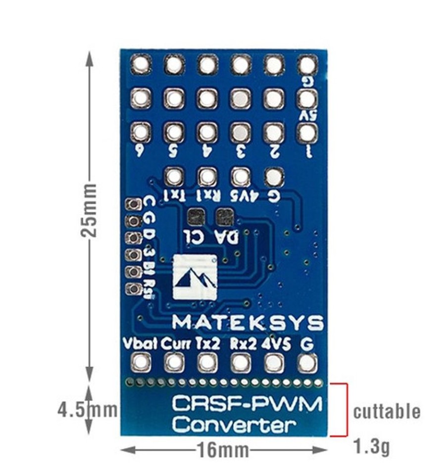
- 25Mm X 16Mm, 1.3G
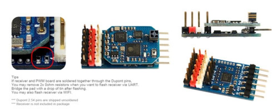
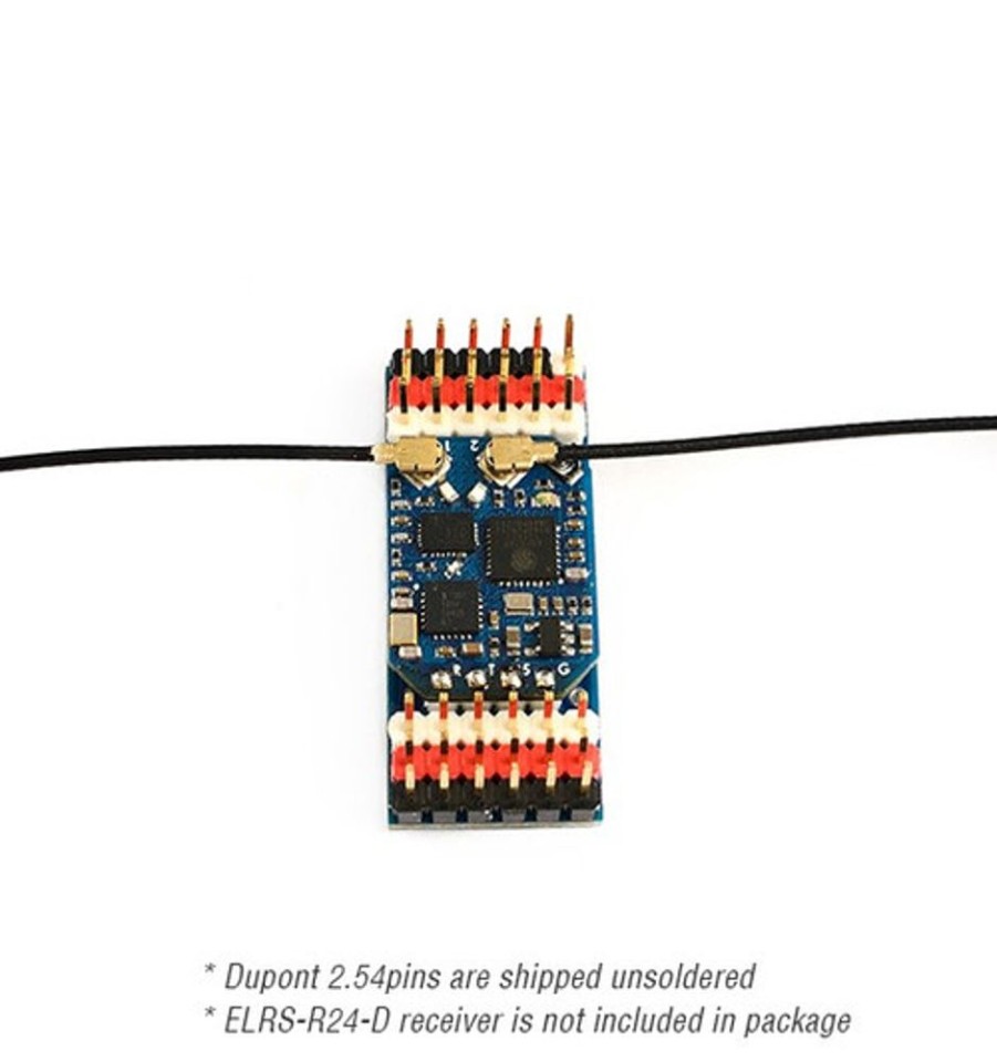
- Packing: 1X Crsf-Pwm-6, Dupont 2.54 Pins
Pinouts And Pads
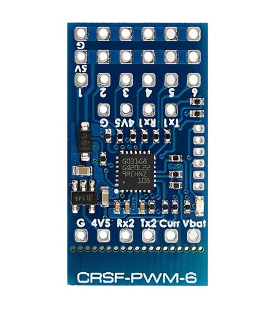
- Tx1/Rx1(Uart1) For Crsf Protocol Receiver
- Tx2/Rx2(Uart2) For Gps/Firmware Update/Setting Parameters
- 1~10: Ch1~Ch10 Pwm Outputs
- Curr: Current Sensor Signal (0~3.3V)
- Vbat(Crsf-Pwm-6 And -C ): (0~36V) Battery Voltage Sensing
- Vbat(Crsf-Pwm-B) ): (6~30V) Battery Voltage Sensing And Power Supply Of Onboard Bec
- G: Ground
- 4V5 Pad Voltage = 5V Pad Voltage -0.3V, &Nbsp;Make Sure The Voltage On 5V Pad Is Not Higher Than Receiver And Gps Rated Voltage.
Failsafe (Fw 1.1.1 Or Older)
- Failsafe Value Is Set Automatically After Crsf-Pwm Board Is Powered On And Receive Crsf Signal. Led Blinks 8 Times Quickly.
- Failsafe Value = The Pwm Value Of Each Channel(Except Ch3) When Crsf Signal Is Received By Crsf-Pwm Board For The First Time
- Ch3 Is Specially Arranged For The Throttle, &Nbsp;Failsafe Value = 988 By Default.
- Usually Put The Throttle &Nbsp;Joystick To The Lowest Point, &Nbsp;Put Ail(Roll), Ele(Pitch), Rud(Yaw) Middle Before Powering On Receiver.
Failsafe (Fw 2.0.0 Or Newer)
- Ch3 Is Arranged For The Throttle, &Nbsp;Failsafe Value = 988 By Default. &Nbsp;You Can Change The Failsafe Value Of Ch3 And Other Channels By Following Settings.
- Make Sure Esc Signal Is Disconnected From Crsf-Pwm Board Before Starting Failsafe Settings
- Bridge Pwm1 And Pwm2 Signal Pad, Then Power On Crsf-Pwm Board And Receiver.
- Failsafe Value Will Be Saved Automatically After Crsf-Pwm Board Is Powered On And Receive Crsf Signal. Led Blinks 8 Times Quickly.
- Failsafe Value = The Pwm Value Of Each Transmitter Channel When Crsf Signal Is Received By Crsf-Pwm Board.
- Remove The Jumper Between Pwm 1 And 2, &Nbsp;Then Crsf-Pwm Board Will Work In Normal Pwm Output Mode.
Led Status
- Slow Blinks: Crsf-Pwm Board Doesn&Rsquo;T Receive Crsf Signal, E.G., Receiver Is Not Bound With Transmitter, Receiver Is Not Connected To Uart1 Of Crsf-Pwm Board.
- 8X Quick Blinks: Crsf-Pwm Board Received Crsf Signal And Failsafe Value Is Saved. (Firmware 1.1.1 Or Older)
- Solid On: &Nbsp;Crsf-Pwm Board And Receiver Are Working Normally
- 2X Slow Blinks Between 8X Fast Blink And Solid On: Cli Mode Is Active &Nbsp;(Firmware 1.1.1 Or Older)
Gps Telemetry
- Compatible With Gps Nmea Protocol, 1Hz, Baud 9600~115200
- Gps &Ldquo;Tx&Rdquo; To Crsf-Pwm Board &Ldquo;Rx&Rdquo; Single Wire Half Duplex Uart Connection, &Nbsp; Crsf-Pwm Board &Ldquo;Tx&Rdquo; To Gps &Ldquo;Rx&Rdquo; Is Not Essential.
- Support Gps Telemetry Id: Gps, Gspd, Hdg, Alt, Sats
- U-Blox Series Gps Can Output &Ldquo;0+1 &Ndash; Ubx+Nmea&Rdquo; Protocol By Default
- Sensors(Gps, Gspd, Hdg, Alt, Sats) Will Blink In Transmitter Telemetry Tab Once Crsf-Pwm Board Has Connection With Gps.
- Troubleshooting For No Gps Telemetry, &Nbsp;Double Check The Wiring Between Gps And Crsf-Pwm Board, &Nbsp;Some U-Blox Gps May Don&Rsquo;T Output Nmea Protcol, You Need To Revert Gps To Default Configuration In U-Center.
- With Opentx Telemetry Logging, You Can Plot Your Flight Path Or Search The Lost Plane.
Vspd Telemetry (Vario)
- Vspd Telemetry Is Supported By Expresslrs 2.0, Edge 2.6, Opentx 2.2 Or Newer.
- Support Barometer Ms5611(I2C Address 0X77) And Spl06-001 (I2C Address 0X76)
Tim &Amp; Pwm Frequency
- Pwm Frequency On All 10X Channels Can Be Configured According To Tim
- Pwm Run At 50Hz By Default
- Tim2: &Nbsp;Ch1, Ch2, Ch4
- Tim16: Ch3
- Tim3: &Nbsp;Ch5, Ch6, Ch7, Ch8
- Tim1: &Nbsp;Ch9, Ch10
Cli Mode
- If Crsf-Pwm Board Doesn&Rsquo;T Detect Gps Connected To Uart2 Within 10 Seconds After Powering On, &Nbsp;Cli Mode Will Active.
- After Cli Mode Is Active, Crsf-Pwm Board Can Be Connected To Configurator Via Usb-Ttl Module/Fc Passthrough.
- In Cli Mode, Crsf-Pwm Board Firmware Can Be Updated
- Cli Mode Has No Effect To Receiver Crsf Signal And Pwm Outputs
Additional Information
Cli Mode And Parameters
Firmware Updates
Elrs-R24-V
(Including 433Mhz, 868Mhz, 915Mhz, 2.4Ghz)
Be the first to review “Accessories | Electronics Matek Matek – Crsf To Pwm Converter (6 Type)” Cancel reply
Related products
Electronics Transmitter & Receiver (Tx & Rx)
Spektrum | Electronics Spektrum Spektrum As3X Programming Cable – Usb Interface
Electronics Transmitter & Receiver (Tx & Rx)
Frsky | Electronics FrSky Frsky R-Xsr 2.4Ghz 16Ch Accst Micro Receiver
Electronics Transmitter & Receiver (Tx & Rx)
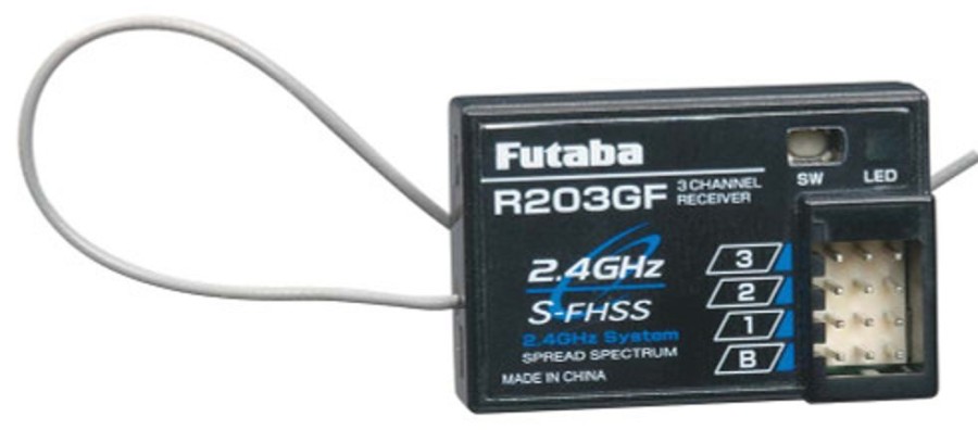
Futaba | Electronics Futaba Futaba 3Prka 2.4Ghz Fhss Radio System W/R203Gf Receiver
Electronics Transmitter & Receiver (Tx & Rx)





Reviews
There are no reviews yet.